Tachistoscope - Setup

Semi-permeable mirror (beam-splitter)
Suppliers:
- Stereoscopic Mirror
- Glass Trösch AG / HY-TECH-GLASS
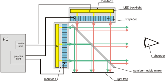
The transmission:reflection-ratio for the semi-permeable mirror should be as close as possible to 50:50 as to allow for matching the luminous output of both monitors, as seen through the mirror, without having to down-regulate one of the monitors too much and thereby reducing the maximal possible luminance.
Moreover, the transmission:reflection ratio should be as independent as possible of the light wavelength and incidence angle. Note, however, that the light coming from the LC-panels is polarized — after all, this is how LC technology works. This can be a problem when assessing the suitability of a semi-permeable mirror, because the mirror performance might also depend on the plane of the light polarization. For the same reason, the mounting position of the mirror, for example which side is up, might play a role.
Mounting rack
Mechanically, a 2-channel tachistoscope is built like some commercially availabe 3-D displays, for example:
However, these devices come with monitors which might not have an LED backlight or are not well suited for the necessary backlight modification. Moreover, the spatial alignment of the two monitors might be sufficient only for stereoscopic presentations but not for the visual stimulation in a tachistoscopic setup.
... aluminum frame
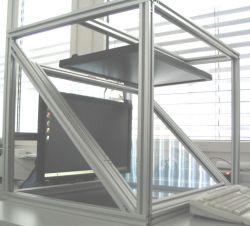
The picture shows a frame built with 3cm x 3cm aluminum profiles. The 50:50 mirror is a single-unit production because of its large size, which is only needed when using the tachistoscope at very long observation distances. Notice the bad quality of the mirror as revealed by the distorted mirror image of the window blinds. The mirror is mounted in its own aluminum frame which slides in the main frame; this is actually overkill as the mirror is stable enough to be supported by just two sides, e.g., the two diagonal profiles of the main frame.
Meanwhile, the mirror was replaced by a 21" x 21" x 1/8" mirror, which works just fine.
The monitors are attached through their standard 10cm x 10cm VESA mount holes (not visible in this picture). There are no special adjustment mechanisms other than the aluminum profiles to which the monitors are attached. Although this provides already many degrees of freedom, it does not cover all. Moreover, the adjustment is cumbersome — loosing the screws holding the profiles in place, changing the profile's position, tightening the screws again... — and requires patience. Moreover, the screw holes in the monitors are rigidly connected to just the plastic housing and not to the LC panel itself, which makes the whole thing more wobbly than one might think, although it stabilizes after some time. Bottom line: a dedicated adjustment mechanism would be a nice feature to have.

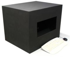
The aluminum rack is covered with a cardboard box which has been painted with black dispersion paint (especially on the inside). Another black cardboard can be put underneath the whole thing and one on top of the mirror, with a cut-out just large enough to make the full screen visible when viewed from the observation distance used in the experiments. The purpose of all the black is to reduce stray light.
... plywood box
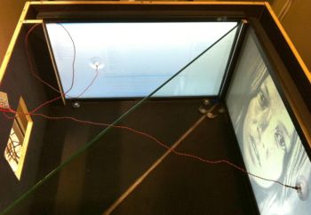
The picture shows a "mounting rack" made of plywood, with the top cover removed and a photo diode attached to each screen for test purposes. The monitors stand on the ground plate and are clamped with their frames against the partition walls and the adjustment widgets on the ground plate. The small cut-out on the left side is where the subject looks into the box, and the whole box is lined with black felt to reduce stray light.
Additional control monitor
At least during the development phase, it is very useful to have either an additional control monitor installed or the possibility to manually disengage the external LED backlight control. Otherwise, it is just too easy to have the LED backlights of both monitors switched off while the program gets stuck or crashes, leaving one sitting in the dark with no other way out but pulling the plug. Moreover, if the LED backlights are controlled via the parallel port and the parallel port happens to boot to the wrong signal levels, one sits in the dark right from the beginning.
Controlling an additional monitor requires a third graphics output or an external video-splitter which is capable of handling the graphics resolution being used. Note that most DVI splitters do not work for dual-link DVI, which would be required for 100Hz monitors. One that does work is the Gefen 1:2 DVIDL.

